Originally Published October 19, 2013
Ever heard the phrase “you just can’t work on cars these days because they’re all computerized”? Well, it’s 2013, and unless you’re an expert with pneumatic engine control systems, you’re probably in better shape working with the Engine Control Module. This post shows you how to connect your Raspberry Pi to a Bluetooth OBD-II adapter and to run a few simple commands.
Equipment List
First off, here’s a list of exactly what I’m using:
- CanaKit Raspberry Pi (512 MB) Basic Kit (Raspberry Pi 512 MB + Clear Case + Micro USB Power Supply)
- Plugable USB Bluetooth 4.0 Low Energy Micro Adapter (Windows 8, 7, XP, Linux Compatible; Classic Bluetooth and Stereo Headset Compatible)
- BAFX Products (TM) – PIC18F2480 Bluetooth OBD2 scan tool – For check engine light and other diagnostics – Android compatible
- 2004 BMW 325i (black)
OBD-II
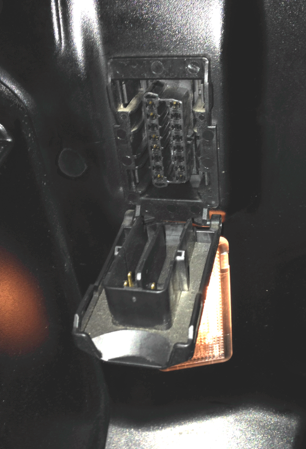
OBD stands for On-Board Diagnostics, and this standard connector has been mandated in the US since the 1996 model year. It’s a 16 pin connector, and by law, it must be within 2 feet of your steering wheel, so it should be pretty easy to find. Mine looks like this with a little door covering it most of the time:
The OBD-II connector is how you can connect to your car’s Controller Area Network (CAN) Bus. You can collect all sorts of real-time information from the CAN Bus through the OBD-II port, and also pull any “Check Engine Light” Malfunction Indicator Lamp (MIL) trouble codes. There are two flavors of MIL codes — those that cause the MIL to light up without flashing, and those that cause it to flash. If your MIL is on, but it isn’t flashing, you have an emissions problem — basically you’re polluting the environment more than you’re supposed to, but your car isn’t really at risk of damaging itself. Lots of things can cause the MIL to light up, your gas cap could be loose, you could have a bad O2 sensor, or your air/fuel ratio may be off. Cars run by burning a precise mixture air and fuel, and if that mixture is off, the car won’t be burning fuel as efficiently as it could be. If your MIL is blinking, you should pull over. Something is very wrong.
OBD-II Modes
The OBD-II specification defines 10 different modes of operation, each with a series of Parameter IDs (PID):
$01. Show current data$02. Show freeze frame data$03. Show stored Diagnostic Trouble Codes$04. Clear Diagnostic Trouble Codes and stored values$05. Test results, oxygen sensor monitoring (non CAN only)$06. Test results, other component/system monitoring (Test results, oxygen sensor monitoring for CAN only)$07. Show pending Diagnostic Trouble Codes (detected during current or last driving cycle)$08. Control operation of on-board component/system$09. Request vehicle information$0A. Permanent DTC’s (Cleared DTC’s)
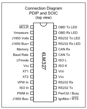
I’ve highlighted some of the more used ones. Mode 09 pulls vehicle information, like the manufacturer of the car, the Vehicle Identification Number (VIN), and other information that doesn’t change. Mode 03 is used to pull any stored trouble codes — these may or may not be causing the MIL to light up. Depending on the code, one or two might just be stored without lighting up the MIL. Mode 01 is full of great real time information like the engine’s current RPM, the current speed, the throttle position, coolant temperature, intake temperature, and all sorts of other sensor information. First off, you’ll want to plug the Bluetooth OBD-II adpater into this port and turn the car on. The Bluetooth adapter uses an ELM327 chip to communicate with the CAN bus over OBD-II. The ELM327 chip is a programmed microcontroller produced by ELM Electronics for translating the OBD interface. The ELM327 command protocol is one of the most popular PC to OBD interface standards, it’s the best way to communicate with the CAN bus over OBD-II.
Once we have the OBD-II adapter plugged in and powered on, we’ll need to connect to it from our Raspberry Pi.
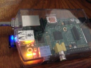
As you can see here, I’ve plugged my Bluetooth USB adapter into it, and I’ll be connecting over SSH for most of the rest of this (though you could just plug in to an HDMI monitor and open the terminal). I’m using Raspbian OS on my Pi, which is a variant of Debian.
There are a few things you’ll need to do to get bluetooth working on your Raspberry Pi. First off, some of this requires you to be root, so unless you’re super concerned about security on your Pi, just do everything else here as root:
pi@raspberrypi ~ $ sudo su root@raspberrypi:/home/pi#
If this is a new Raspberry Pi, and you haven’t already updated the apt-get package manager, you’ll want to do that now:
# apt-get update
*# apt-get upgrade*
These will take awhile to run, so go have a coffee or something. Once apt-get is up to date, you’ll want to enable DBus:
# update-rc.d -f dbus defaults
D-Bus is a message-bus system, a way for applications to talk to one another. It works with Unix sockets between applications and daemons. It is needed by Bluez, which we’ll be installing in a moment. At this point, however, you should restart your Pi:
# reboot
After logging back in and re-entering root mode, you can then install a few bluetooth tools using apt-get:
# apt-get install bluetooth bluez-utils blueman
Now if you list the USB devices on your Pi, you should see the Bluetooth dongle connected (mine is the Broadcom Corp one below):
# lsusb
Bus 001 Device 002: ID 0424:9512 Standard Microsystems Corp. Bus 001 Device 001: ID 1d6b:0002 Linux Foundation 2.0 root hub Bus 001 Device 003: ID 0424:ec00 Standard Microsystems Corp. Bus 001 Device 004: ID 0a5c:21e8 Broadcom Corp.
Assuming everything is working, you should be able to scan for available bluetooth devices nearby with hcitool:
# hcitool scan
Scanning ... CC:6D:A0:11:08:66 Roku Player 00:0D:18:A0:4E:35 OBDII 00:0D:4B:F0:CB:6E Roku Player
You can see here, I have a few Roku boxes on nearby TVs and my OBDII adapter has an address of 00:0D:18:A0:4E:35. If the hcitool scan didn’t work, you can check to make sure bluetooth is enabled with an hciconfig command:
# hciconfig hci0: Type: BR/EDR Bus: USB BD Address: 00:02:72:C6:A6:81 ACL MTU: 1021:8 SCO MTU: 64:1 UP RUNNING PSCAN RX bytes:121283 acl:138 sco:0 events:12710 errors:0 TX bytes:70273 acl:104 sco:0 commands:12591 errors:0
If that didn’t work, you can check your bluetooth status:
# /etc/init.d/bluetooth status
And (re)start it if need be.:
# /etc/init.d/bluetooth [stop/start/restart]
At this point, you can pair with the Bluetooth OBD-II reader using Bluez:
# bluez-simple-agent hci0 00:0D:18:A0:4E:35
You might be prompted to enter a PIN at this point, but I wasn’t. If you are, try “1234” with this adapter. Others use “0000”. You can then make the adapter trusted so you don’t have to manually pair with it every time it becomes available:
# bluez-test-device trusted 00:0D:18:A0:4E:35 yes
At this point, after monkeying around with a variety of different bluez commands to try to connect form the command line, I gave up and launched a VNC session to us Preferences => Bluetooth Manager. You could also just plug in to a monitor, but here’s how to set up VNC if you don’t want to use a monitor:
# sudo apt-get install tightvncserver
# tightvncserver
# vncserver :0 -geometry 1920x1080 -depth 24
Once you’ve connected, you’ll have a new device at */dev/rfcomm0 *with which to communicate.
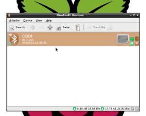
To begin to communicate with /dev/rfcomm0, you’ll want to install screen:
# apt-get install screen
And then connect to /dev/rfcomm0 with Screen. Screen is a full-screen window manager that multiplexes a physical terminal between several processes, typically interactive shells:
# screen /dev/rfcomm0
Within Screen, you’ll be able to enter a number of commands. First off, you should know about some of the AT commands. These commands are system commands that mimic some of the AT “ATtention” commands of the old Hayes Modem command set. Remember “ATDT” (ATtention Dial Tone)?
First off, you’ll want to set up some formatting options, because the default is to jumble responses on top of queries, making them hard to read:
> ATZ
Restarts the device. You’ll need to do this from time to time.
> ATL1
Turns linefeeds on
> ATH1
Turns headers on
> ATS1
Turns spaces on
>ATSP0
Set the protocol to Auto
These commands should all return a simple “OK” response from the ELM327 chip. If you want information about that chip, you can enter:
>ATI ELM327 v1.5
But that’s all pretty boring. Let’s start querying some information from the car! First off, let’s see if we have any stored MIL trouble codes with a mode 03 query:
>03 SEARCHING... 87 F1 12 43 04 44 00 00 00 00 15
I do have a stored error code of 0444 (I’ve left my gas cap loose to cause it for this demonstration). The response here is shown as a sequence of hex pairs. Directly in front of the 0444, you’ll see a “43”. This is saying that it is a response to a 03 query (the 4 indicates a response, the 3 is the query it’s responding to). The rest can be ignored.
What about pulling the VIN? That’s a mode 09 query with a PID value of 02, so we enter:
>0902 87 F1 12 49 02 01 00 00 00 57 2D 87 F1 12 49 02 02 42 41 45 56 F5 ...
This actually returns 5 frames (lines) of data for the entire encoded VIN, but I don’t really want to post my VIN to the world, so I’ve truncated the last 3 lines above. You can also pull real-time information. Here’s an example of pulling the current RPM of the engine. Real-time data is a Mode 01 query, and the RPM query is a PID of 0C:
>010C 84 F1 12 41 0C 0A DC BA
Again, we have some hex data, so how do we decode it? We’re interested in the two pairs after the response indicator, which in this case is “41 0C” (4 for the response, 1 because it was a mode 1 query, and 0C because the PI was 0C). The RPM response is reported in quarters of an RPM (don’t ask me why), and OADC in hex equals 2780 in decimal. 2780 divided by 4 = 695*RPM* which is basically just idling.
Here’s a screen capture of this basic process using the screen command:
So that’s it, that’s the basics of how to connect a Raspberry Pi to your OBD-II port on a car via Bluetooth.
Hint: you can quit out of Screen with Ctrl-A, Ctrl-D.
Here are some great places for more information:
